Simbeor Simulation Technology
The core solvers of Simbeor are based on the following methods:- Method of Lines (MoL) for 3D stratified circuits;
- Trefftz Finite Element Method (TFEM) for 2D and 3D geometries and for conductor interior modeling;
- Method of Simultaneous Diagonalization (MoSD) for precise transmission line and multiport parameters extraction.
Method of Lines have been discovered by M.G. Slobodianskiy in 1939 and extensively developed later in works of V.N. Faddeeva, L.V. Kantorovich and many others. Application of the method to practical electromagnetic problems have been developed by R. Pregla, U. Schultz, S.B. Worm, W. Pascher, Y.O. Shlepnev and many other researchers in 80s and 90s. Numerical efficiency and simplicity are the major features of the method and its development is an ongoing effort.
Method of Lines is a partial discretisation technique similar to the Method of Moments (MoM). Maxwell's equations with all six components of electromagnetic field are approximated by a differential-difference system that is reduced to a system of linear equations using discrete analogue of the spectral domain technique developed earlier in MoM. MoL uses grid Green’s functions that are discrete analogues of the MoM Green’s functions of multilayered media. The final system of linear equations relates only discrete electric and magnetic currents on some surfaces of the problem that is also similar to the MoM. The system matrices are filled with a fast algorithm based on FFT that is again similar to some
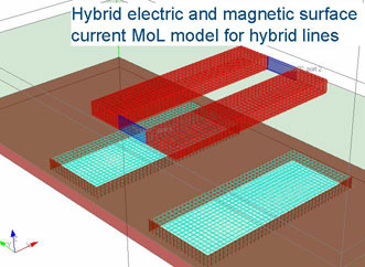 implementations of MoM. Mapping a problem on the grid from the beginning, instead of meshing surfaces at the final stage of solution, is the only difference of the MoL but it gives a self-regularized solution with only one parameter defining the whole numerical model (grid cell size) that leads to monotonous convergence of calculated data and predictability of calculation errors. A final system of equations can be solved either with an iterative method without filling the matrix (matrix-less algorithm) or with a direct method based on a matrix order reduction technique. Due to internal symmetries, only one row and column of the matrix have to be stored for the iterations or for the order reduction processes. For the direct solution, a matrix order reduction technique called super-grid can be used to overcome the restriction of the regular grid and to reduce the final system. The super-grid technique is based on projection of the large matrix into small one using linear or higher order re-expansions and bundling some grid cells to reduce the number of variables in areas with slow changing currents.
The high grade of internal symmetries of the regular grid-based algorithms of the MoL reduces substantially the numerical complexity of the problems and allows to solve them with the benchmark accuracy. In addition, the simplicity of the MoL makes it possible to create highly optimized and versatile software.
MoL combines advantages of finite-difference and MoM techniques:
- Reduces problem dimension to surfaces of metal and cut-outs
- Provides monotonous convergence and predictable simulation error
- Algorithms are straightforward and simple for software development
- Takes into account metal thickness
- Easy to hybridize with Trefftz finite elements for conductor interior modeling
- Incommensurability of large homogeneous air and dielectric domains and small circuit elements of planar problems results in limited capabilities of 3D tools (long simulation or low accuracy)
- Adaptation or optimization of a 3D finite-difference method to the planar 3D structures leads naturally to formulation similar to MoL
- Mismatch between continuous spatial field representations and discrete current meshing could result in the relative convergence phenomena (R. Mittra, T. Itoh, T-S. Li – IEEE Trans, v. MTT-20, N2 1972).
- Non-regular meshing leads to computationally complex and slow algorithms or to inaccurate results (some 2.5D and 3D MoM solvers)
- Regular meshing provides fast FFT-based algorithms with good convergence and leads to a formulation similar to the MoL (some 2.5D solvers)
- M.G. Slobodianskiy, “Method for approximate integration of partial differential equations and its application to problems of elasticity theory (in Russian)”, - Prikladnaia Matematika i Mekhanika, 1939, v. 3, N 1, p. 75-82.
- V.N. Faddeeva, “Application of the method of lines to some boundary-value problems (in Russian)”, - Trudy Matematicheskogo Insttuta AN CCCP, 1949, v. 28, p. 73-103.
- L.V. Kantorovich, V.I. Krylov, “Approximate methods of computational mathematics (in Russian)”, Fizmatgiz, Moscow, 1962, 708p.
- U. Schulz, R. Pregla, “A new technique for the analysis of the dispersion characteristics of planar waveguides”, Arch. Elec. Ubertragung, v. 34, 1980, p. 169-173.
- S.B. Worm, R. Pregla, “Hybrid-mode analysis of arbitrarily shaped planar microwave structures by the method of lines”, - IEEE Trans. on MTT, 1984, v. 32, N2, p. 191-196.
- R. Pregla, W. Pascher, “The method of lines”, in Numerical techniques for microwave and millimeter-wave passive structures, Edited by T. Itoh, J. Willey Publ., New York, 1989, p. 381-446.
- Y.O. Shlepnev, Method of lines in mathematical modeling of MIC's planar elements (in Russian). - Thesis of Candidate of Technical Sciences (Ph.D.). - Novosibirsk, NEEIC, 1989
- A.G. Vikhorev, Y.O. Shlepnev, “Analysis of multiple-conductor microstrip lines by the method of lines”, - Journal of Communications Technology and Electronics, 1991, N 12, p. 127-129, originally published in Radiotekhnika i Elektronika, v. 36, 1991, N 4, p. 820-823.
- Y.O. Shlepnev, “Extension of the Method of Lines for planar 3D structures”, - in Proc. of the 15th Annual Review of Progress in Applied Computational Electromagnetics (ACES'99), Monterey, CA, 1999, p.116-121.
Trefftz Finite Element Method (TFEM)
Trefftz finite element method has been based on the method of Minimum Autonomous Blocks (MAB) developed by V.V. Nikol’skiy and T.I. Lavrova-Nikol'skaia in the late 70s, early 80s and on theory of balanced node of Transmission Line Matrix (TLM) method discovered by B.V. Sestroretskiy in 1983. Both MAB and TLM methods have been later derived by Y.O. Shlepnev with Trefftz-type technique outlined below. Note, that this approach was recently rediscovered by some researches as Ultra-Weak Discontinuous Galerkin’s Method (UWDG).
Here is a brief description of the TFEM. A problem is decomposed into a set of polytope or polygonal elements like in the conventional finite element method. Electromagnetic fields inside the elements are expanded into a finite number of plane-wave solutions of Maxwell's equations. Radial or spherical waves can be used as the intra-element basis functions as well. An additional set of basis functions is defined on the surface of the element and is used to project the intra-element fields on the surface and to build admittance or scattering descriptors of the element. The surface basis functions contain both electric and magnetic fields and have to satisfy some additional orthogonality conditions.
 Projection of the interior fields on the surface can be done with a point matching projectors that leads to TLM-type elements that were termed as the elements of Trefftz-Sestroretzkiy. Galerkin-type projectors lead to MAB-type elements. They are called elements of Trefftz-Nikol'skiy. Note that only the Galerkin's projector guarantees conservative property of the element that is not valid for the elements obtained with the point matching projectors in general. Simple matrix equations can be constructed to calculate the element descriptors. With this approach, each Trefftz element represents a small volume in the space as a multiport with its admittance or scattering matrix descriptors. Connection of those multiports is equivalent to superimposing of the continuity of electric and magnetic fields on the surfaces of the elements. Thus, the boundary value problem is reduced to a simple re-composition of the descriptor matrices of the multiports characterizing the Trefftz elements. Note, that the intra-element fields may be discontinuous at the boundaries of the elements.
The approach has some advantages over the conventional finite elements. First of all, the fields inside the elements are always exact solutions of the homogeneous Maxwell's equations by definition. This fact makes it possible to simulate problems with huge variations in properties of materials with commensurable element size for all materials. Size of an element is not restricted by a wavelength or skin depth if the interior expansion waves include eigenwaves of a structure represented by the element. Integration only over the element boundaries is required to build an element. It can be done analytically in most cases. No inter-element continuity conditions are required at the element building stage. Admittance or scattering matrix descriptors provide simple way to assemble a global matrix, to impose impedance boundary conditions and to link the method to the Method of Lines or to the circuit theory. Element building procedures for brick, polygonal and polytope elements in general have been built.
References on the Trefftz Finite Element Method
- V.V. Nikol’skiy, T.I. Lavrova, “The method of minimum autonomous blocks and its application to waveguide diffraction problems”, Radio Engineering and Electronic Physics, vol. 23, no. 2, p.1-10, 1978.
- V.V. Nikol’skiy, T.I. Nikol'skaia, Decompositional approach to electromagnetic problems (in Russian). Moscow: Nauka, 1983.
- B.V. Sestroretzkiy, “Balanced RLC- and R-tau circuits of elementary volumes of space (in Russian)”, - Voprosy Radioelektroniki, ser. OVR, no. 5, p. 56-85, 1983.
- Y.O. Shlepnev, “Trefftz-type brick finite elements for electromagnetics”, - in Proc. of the 17th Annual Review of Progress in Applied Computational Electromagnetics (ACES'2001), Monterey, CA, March 19-23, 2001, p. 345-352.
- Y.O. Shlepnev, “Trefftz finite elements for electromagnetics”, - IEEE Trans. Microwave Theory Tech., vol. MTT-50, pp. 1328-1339, May, 2002.
- Y.O. Shlepnev, “Polygonal Trefftz finite elements for electromagnetics”, - in Proc. of the 18th Annual Review of Progress in Applied Computational Electromagnetics (ACES'2002), Monterey, CA, March 18-22, 2002, p. 327-334.
- Y.O. Shlepnev, “Building Trefftz finite elements for electromagnetic problems”, - in Mathematical Methods in Electromagnetic Theory (MMET'2002), Kiev, Ukrain, p. 488-490, September 2002.
- Y.O. Shlepnev, “T-elements for 3D electromagnetic problems”, - in Proc. of the 19th Annual Review of Progress in Applied Computational Electromagnetics (ACES'2003), Monterey, CA, March 2003.
- Y.O. Shlepnev, “Scattering matrix descriptors of Trefftz finite elements”, - in Proc. of the 20th Annual Review of Progress in Applied Computational Electromagnetics (ACES'2004), Syracuse, NY, April 2004.
Method of Simultaneous Diagonalization (MoSD)
Method of simultaneous diagonalization is the method to extract characteristics of transmission line eigenwaves and to extract multimode generalized S-parameters from results of computational electromagnetic analysis. To find and to match eigenmodes in a line segment, auxiliary sources located in regions at the opposite sides of the segment are used. Assuming that there is a limited number of eigenwaves propagated in the line and that these eigenwaves should be ideally matched in the sources regions, a system of two or four nonlinear matrix equations is constructed and solved by simultaneous diagonalization of two or four matrices with congruence and shift transforms. Solutions of the diagonalized system are propagation constants and characteristic impedances of the eigenmodes, and parameters of the sources that in
 its turn make it possible to calculate generalized scattering matrices of the line segments and S-matrices of discontinuities.
The method is based on the idea that any propagated eigenwave of a line can be excited without reflection using a proper system of surface sources. The MoSD may be considered as an extension of the Method of Passing Through a Layer (MPTL) suggested by V.V. Nikol’skiy and T.I. Nikol'skaia in 1983. In MPTL, the complete cross-section of a transmission line segment is used to calculate admittance or transfer matrix and to set up a system of equations to find parameters of the eigenwaves using simultaneous diagonalization. Just one line segment, that is usually one slice of grid of the meshed line cross-section, is enough to find eigenwaves and scattering matrix extraction parameters with MPTL. The MPTL was later generalized in works of Y.O. Shlepnev, V.Y. Kustov and B.V. Sestroretzkiy as MoSD. The MoSD is developed to use portions of a line cross-section or even areas perpendicular to the line cross-section to calculate characteristics of eigenwaves and to extract multi-mode S-parameters. Such problems arise in electromagnetic simulation of discontinuities in planar transmission lines with methods similar to the method of moments or to the method of lines.
The method has been recently extended for extraction of non-orthogonal modes of lossy multiconductor lines. Because of 3D nature, the lossy formulation of MoSD can be used to extract parameters of periodic structures and periodically disrupted multiconductor lines without any modification. Note also, that the characteristic impedance extracted with the MoSD is close to 3D impedance definition of J. Rautio and can substantially deviate from classical 2D definitions such as P-I, P-V or V-I at high frequencies. So far the 3D impedance definition is the closest to the experimental results at least for strip and microstrip lines.
References on the Method of Simultaneous Diagonalization
- V.V. Nikol’skiy, T.I. Nikol'skaia, Decompositional approach to electromagnetic problems (in Russian). Moscow: Nauka, 1983.
- Y.O. Shlepnev, Method of lines in mathematical modeling of MIC's planar elements (in Russian). - Thesis of Candidate of Technical Sciences (Ph.D.) - Novosibirsk, NEEIC, 1989.
- Rautio J.C. “A new definition of characteristic impedance”, - in MTT Int. Symposium Digest, June 1991, Boston, p.761-764.
- Y.O. Shlepnev, B.V. Sestroretzkiy, V.Y. Kustov, “A new approach to modeling arbitrary transmission lines”, - Journal of Communications Technology and Electronics, v. 42, 1997, N 1, p. 13-16, originally published in Radiotekhnika i Elektronika, v. 42, 1997, N 1, p. 13-16.
- Y.O. Shlepnev, “A new generalized de-embedding method for numerical electromagnetic analysis”, - in Proc. of the 14th Annual Review of Progress in Applied Computational Electromagnetics (ACES'98), Monterey, CA, March 16-20, 1998, v.II, p. 664-671.